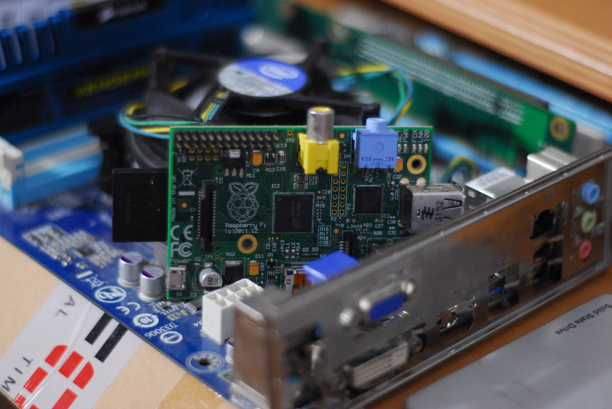
Hopefully this isn’t a contentious opinion: the Raspberry Pi is a terrible desktop computer.
The design just isn’t meant for this – micro HDMI means horrible adapters, the only way to get fast reliable storage is through USB, expansion often needs obscure “hats” that sit on top of the Pi’s mainboard and many of the connectors that are on there are useless in a desktop scenario. And that’s before we get to the form factor.
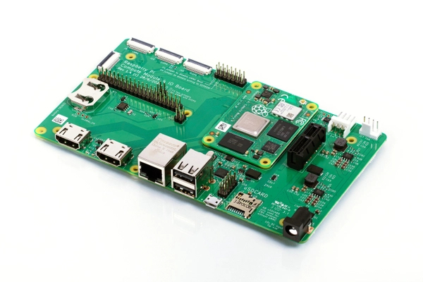
Enter, the new Raspberry Pi Compute Module 4, and more importantly – enter the Raspberry Pi Compute Module 4 I/O Board. It has all the connectors along one edge, PCIe expansion, internal power connectors and supports eMMC and NVMe storage – neither of which is available on the standard Pi 4. Plus, the RTC is pretty much a key requirement for any desktop or server computer. Unfortunately there are also some drawbacks. For one, that PCIe 1x slot has a closed back, so no chance of mounting a 4-lane ethernet or SCSI card in there. Second, while it looks similar to VIA’s Nano-ITX standard, this board won’t mount in an ATX case. And while we now have full size HDMI connectors, and everything external in one row – there’s also a lot wasted on the internal side.
For one, the power connector is from a floppy disk drive. Neat, but not very useful as a desktop. It deeply limits our flexibility on power supplies, and harshly caps the current input the board can accept. On expansion, a single PCIe lane does cap our bandwidth at around 5Gbps, but using a PCIe switch chip this could be shared among multiple devices to at least give much lower latency. As a hypothetical example, a system could be equipped with an NVMe drive for the OS, a bulk storage controller (SATA, iSCSI, Fibre Channel) and an accelerator card such as an Edge TPU – all at the same time. Most desktop scenario’s aren’t going to need high-bandwidth access to both boot drive and external storage at the same time – and even split 50/50, this scenario gives far more speed to each than a fast SD card and USB2 hard disk would have combined – the standard way of doing this on earlier Pi’s.
As for the more exotic connectors, There’s not much call to put a webcam inside an ATX case, but others have shown ways to put those inputs to better use, and as one of them is 4-lane that IC could potentially support simultaneous 720p (say, from an external camera) and 1080p (say, from a games console) for a highly efficient stream box. Even outside the world of streaming, a HDMI-in port could offer a high quality webcam source for video conferencing or a simple way to monitor another headless device – such as another pi, during development work. The IC even supports an i2s output that is compatible with the Pi – paired onto the 1080p input this allows capturing audio from a console, or if only one input is needed – audio from a camera to avoid having a microphone attached to the USB bus.
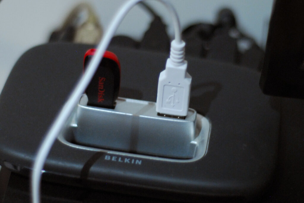
Speaking of, there’s one opinion I have that’s pretty contentious. I don’t care about USB3. I really don’t. My gaming PC has bluetooth (sound out), USB mixer (sound in), Webcam (1080p), keyboard, mouse, 360 controller receiver, a flash drive and a midi controller, all hooked onto a single USB 2.0 hub, on a single USB 2.0 port. It has all the bandwidth I need. So I definitely wouldn’t consider a USB 3.0 controller as being appropriate for an ATX-pi. As with the CM4 I/O board, any USB 3.0 needs can easily be met by using a PCIe card – even more so in this case, as it would not consume the only PCIe slot. A 2.0 hub to break out the single host port into two external type A ports, and both an internal type-A and internal header (for interesting internal devices like a USB-Sata adapter or a USB-floppy interface) would be plenty adequate.
And this illustrates the philosophy of this concept nicely – the point is to (where possible), avoid consuming internal connectivity. The i2c and i2s buses are sadly needed to provide the HDMI inputs. But otherwise, it’s important to try and give as much connectivity as possible. Which brings me nicely onto a short history lesson. While for a lot of people, the GPIO connectivity on a “desktop OS” was completely novel when the Pi was launched in 2012. It’s certainly not something that would be found on an iMac, or a Dell Ultrabook. However, that doesn’t mean it was the first such implementation. Way back in the nineties, a computer company called Be, Inc designed a computer meant to compete with Apple in the education and media markets. It was a very powerful dual-core PowerPC machine – a full four years before the first dual-core Apple Mac, that had world-beating multimedia performance. It also had a 37 pin connector (the “GeekPort”) on the back that exposed spare GPIO, analog inputs and other connections from the internal logic – so that creative hackers, particularly in education, could attach experiments and projects to the computer. Even stealing i2c and i2s for our camera input, the Pi CM4 provides plenty of pins that can be routed to such a connector, including SPI, UART, and two analog-inputs provided by the power management IC.
This provides a much more usable way to work with the Pi’s GPIO on a desktop computer, and I could easily see a simple, passive GeekPort to HAT interface to put these easily within reach on a desktop for breadboarding. Throw in a front-panel connector using the CM4’s reset, power-on and LED pins and we can easily build a complete ATX board that provides all the needs of a desktop computer from that diminutive little clip-on card. The GeekPort itself could also easily be a panel mount attached to an internal HAT – type connector (though, not pin compatible if we want Analog-in) that could also be routed to an internal or front-panel device if preferred.
Wow, you might be thinking. A hacker friendly desktop PC mainboard, with a super efficient Pi in it? Supporting dual HDMI in, dual HDMI out, a 90’s GeekPort, three PCIe slots and NVMe to boot!? When will it be available? How much will it cost? What’s your kickstarter page? And the answer to those questions is: It’s 2020. We don’t get nice things. For one, Kickstarter (and the other “pre-vestment” websites, for that matter) is a nest of scams and villainy that you should avoid like the plague – and two, I have no idea what I’m doing! I can look at datasheets or existing products and work out what components will link together in a useful way, but I can barely design a PCB with a sharpie, much less work with high-frequency signal routing. This isn’t a product brief, it’s just a manifesto for what I’d like to see done (and which I know could be). As far as a price? With a PCIe switch chip, USB hub, two HDMI-CSI converters and all the other little things that go into this; you’d be talking about £200 minimum, at scale. More like £500 to hack one together yourself if you already had the tools.
If someone wants to take this idea and make it their own product? This is officially prior art. You can make and sell this all you like but I require two things in return: “https://inthe.study” silkscreened legibly on the board, and two of the production models shipped to me at no cost and tax paid, to keep. 😉
But I’ll even do you a video review!
Next week: I design a CM4 Laptop.
Supplementary notes
Basic Spec Proposals
- Micro-ATX form factor for wide case compatibility.
- Pi CM4 Carrier socket.
- Breakout main interfaces: Ethernet, HDMI0, HDMI1 – on IO shield.
- Replace GPIO header with a BeBox style D37F “Geekport” on IO shield (not pin for pin compatible).
- ATX 24 pin power
- Ship with I/O shield with mount for Pi Wifi/BT antenna
- Expose SD bus on CM4Lite (sd0) as header pins, plus reset header for programming eMMC though sd0
- Front panel header – GLOBAL_EN (latch to 3.3v to disable when on), RUN_PG (reset), LED_PWR, LED_nACT (HDD)
Expander IC’s
- USB2514B-I/M2 USB 2.0 4-port hub. 2xA ports on io shield, 1xheader, internal 1xA port (for internal USB-storage adapter)
- PCIe 2.0 4-port switch chip. Break out as three 16x (1x) slots 0 2 and 3, with one NVMe M key between 0 and 2
- PCF85063AT RTC with 2032 battery holder
- TC358743XBG HDMI-CSI x2, one 1080p60 and one 1080p25 HDMI input on IO shield